UniFi Camera VLAN Isolation for Local NVR Recording
Configure a UniFi camera VLAN that blocks WAN access, keeps RTSP recording local, and gives the NVR exactly the access it needs.
Configure a UniFi camera VLAN that blocks WAN access, keeps RTSP recording local, and gives the NVR exactly the access it needs.
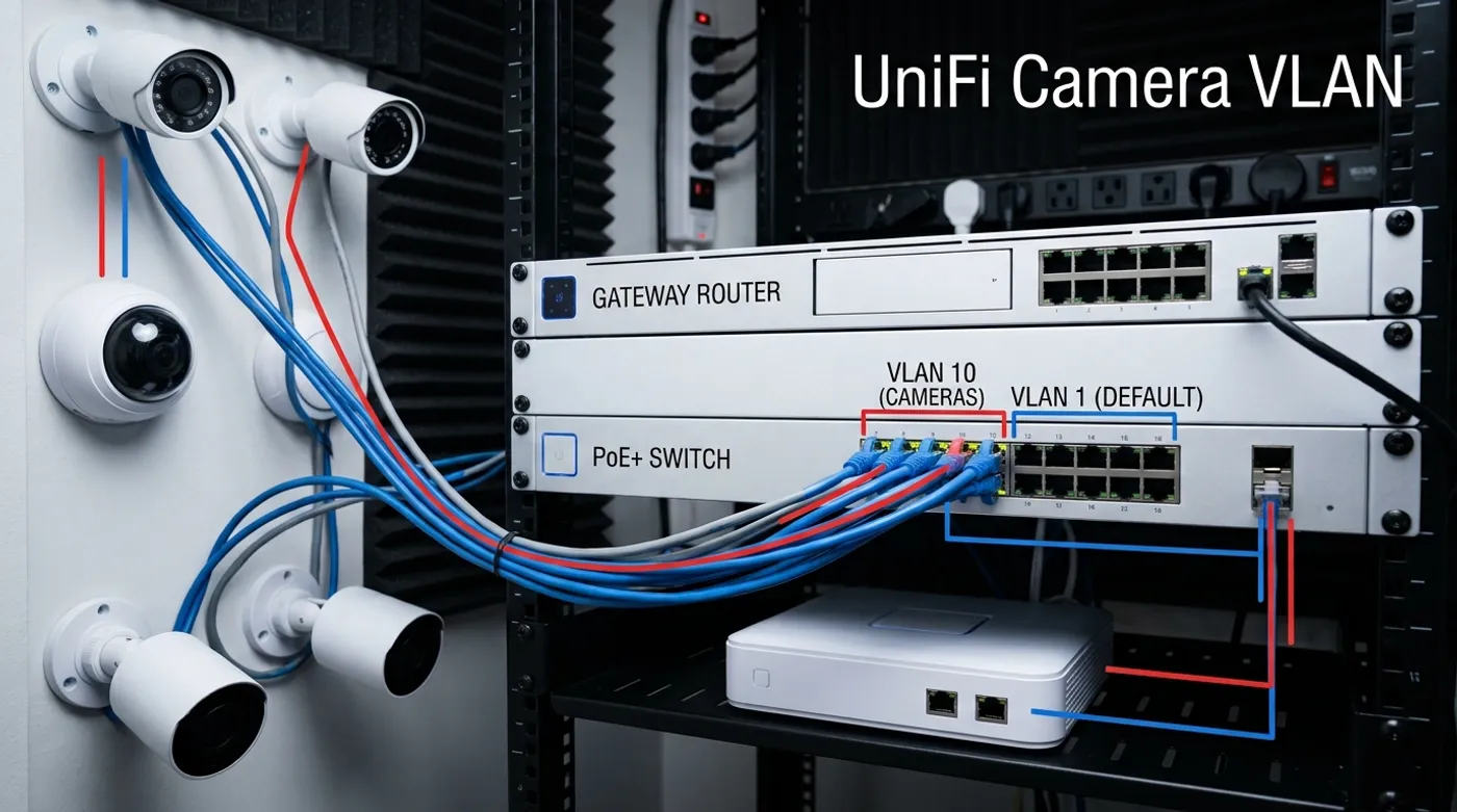
This draft assumes a UniFi gateway such as a UDM Pro, UDM SE, Cloud Gateway, or equivalent UniFi gateway, plus a UniFi PoE switch for wired cameras. The target is not a generic “secure camera network.” The target is a specific UniFi design: cameras on a dedicated VLAN, local NVR access allowed, WAN access blocked, and management exceptions kept narrow.
The SERP around this topic is dominated by Reddit, forums, and YouTube because most users get stuck between two bad defaults. They either leave cameras on the main LAN because it works, or they isolate the VLAN so hard that the NVR stops recording. In UniFi, the cleaner path is to build the camera network first, assign ports deliberately, then create traffic and firewall policy around the NVR.
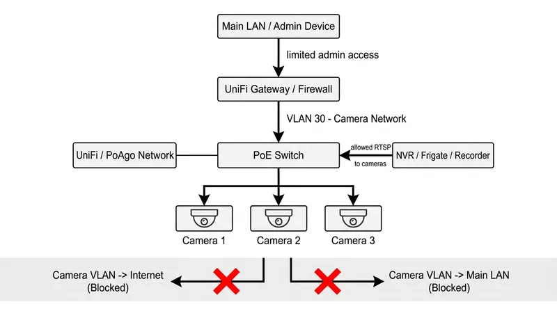
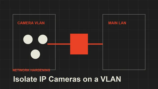
The UniFi Isolation Architecture
Use VLAN 30 for cameras and subnet 10.30.0.0/24. Put camera switch ports in that VLAN as access ports. Keep the NVR on an infrastructure network, for example 10.10.0.50, unless your NVR appliance is physically tied to the camera switch and you intentionally want it inside the camera VLAN.
The policy goal is simple: cameras can talk to the local infrastructure they need, but they cannot initiate traffic to WAN or the main LAN. The NVR can initiate traffic to cameras. Admin access is either from a single workstation or opened temporarily during maintenance.
Create the Camera Network in UniFi
In UniFi Network, create a dedicated network for cameras with VLAN ID 30 and subnet 10.30.0.0/24. Use the UniFi gateway as the gateway for the subnet at 10.30.0.1. Enable DHCP for the camera subnet, but plan to reserve each camera address.
Use a reserved range like this:
- Gateway:
10.30.0.1 - Cameras:
10.30.0.21to10.30.0.80 - Future camera expansion:
10.30.0.81to10.30.0.120 - Infrastructure exceptions: avoid placing the NVR here unless the design requires it
In Port Manager, assign each wired PoE camera port to the camera network as the native or untagged network. Cameras normally should not receive tagged VLAN traffic directly. The switch uplink back to the gateway should carry the camera VLAN as tagged traffic.
Reserve Camera IP Addresses Before Locking Down Rules
Do not build firewall rules around random DHCP addresses. In UniFi, identify each camera by MAC address and create DHCP reservations inside the camera network. Use a naming pattern that will still make sense six months later:
cam-front-door->10.30.0.21cam-driveway->10.30.0.22cam-garage->10.30.0.23cam-backyard->10.30.0.24
Then configure the NVR using those stable addresses. If the recorder uses RTSP URLs, keep the URL inventory in a password manager or documentation file, not only inside the NVR UI. A VLAN design is easier to debug when camera identity, IP address, switch port, and physical location all line up.
Allow the NVR Into the Camera VLAN
The NVR exception should be narrow and directional. The NVR needs to reach the cameras; the cameras do not need to initiate connections back into the NVR network.
For a typical recorder, allow from NVR IP 10.10.0.50 to camera subnet 10.30.0.0/24 for:
- RTSP, commonly TCP
554 - HTTP, commonly TCP
80, if snapshots or admin access require it - HTTPS, commonly TCP
443, if the camera web interface or API uses it - ONVIF or vendor discovery ports only if your recorder actually depends on them
Avoid a broad “Main LAN to Camera VLAN: allow all” rule. It works, but it turns the camera VLAN into decoration. If you need an admin workstation, create a separate rule from one trusted workstation IP to the camera subnet, and disable or tighten it after commissioning.
Block Camera WAN Access
Create a rule that blocks the camera network from reaching the internet. In UniFi terms, this usually means a traffic or firewall rule matching source network Camera VLAN and destination Internet or WAN, with action Block.
The important detail is ordering. Allow local infrastructure first if UniFi evaluates your rules in a way that requires specific allows before broader blocks. Then block camera-originated access to WAN and to other internal networks.
A practical policy set is:
- Allow NVR
10.10.0.50to camera subnet10.30.0.0/24on required ports. - Allow camera subnet
10.30.0.0/24to local NTP at10.30.0.1or another trusted local host. - Allow or redirect camera DNS only if required.
- Block camera subnet to WAN.
- Block camera subnet to main LAN and sensitive internal networks.
If a camera vendor app stops working after this, that is expected. You removed the vendor cloud path. Decide whether the app is more important than local-first isolation before adding exceptions.
Local NTP and DNS in UniFi Camera Networks
Time matters. Security footage with wrong timestamps is hard to correlate with door events, alarms, logs, and Home Assistant automations. Cameras should use local NTP. If UniFi’s gateway or another internal host provides NTP, point cameras there. If cameras insist on public NTP names, redirect or document that behavior before allowing broad internet access.
DNS is different. Many cameras do not need DNS at all for local RTSP recording. If a camera keeps trying to resolve vendor domains, blocking DNS can make the dependency visible. A stricter setup blocks external DNS and allows only local resolver access. A more permissive setup lets cameras resolve names but still blocks WAN, which helps you observe vendor behavior without allowing traffic out.
Do not open full WAN just because DNS logs look noisy. DNS resolution is not the same as a justified outbound connection.
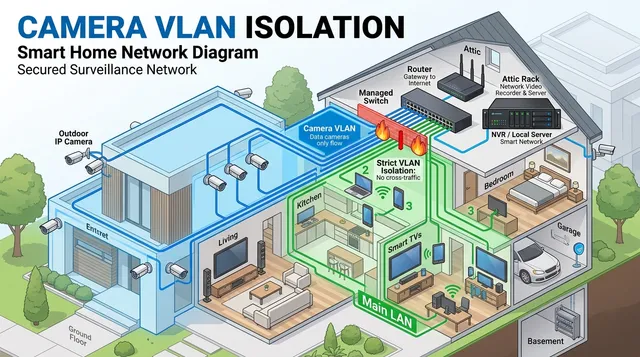
Should UniFi Cameras Be on a Separate Network?
For third-party IP cameras, yes. For UniFi Protect cameras, the design depends on the Protect appliance and adoption model, but the same principle applies: camera devices should not be mixed casually with user devices. Keep camera traffic predictable and keep recording local.
If the cameras are third-party RTSP cameras feeding Frigate, Blue Iris, Synology Surveillance Station, or another local NVR, VLAN isolation is straightforward. If the cameras are first-party UniFi Protect devices, verify adoption, controller visibility, and firmware update behavior before applying the strictest blocks. The target is still containment, but the exact exception list may differ.
Verification Checklist
After applying the rules, verify behavior from the NVR, from a normal laptop, and from the camera VLAN.
- Each camera receives the expected reserved IP in VLAN
30. - Each PoE camera port is assigned to the camera network, not the main LAN.
- The switch uplink carries VLAN
30. - The NVR can pull every camera stream.
- A normal main LAN client cannot browse to camera admin pages.
- Cameras cannot reach the WAN.
- Cameras keep correct time through local NTP.
- DNS behavior is either blocked, local-only, or intentionally allowed.
- Home Assistant or automation events still work through the NVR path.
When the setup is correct, UniFi becomes boring in the right way: camera ports are predictable, the NVR sees what it needs, and the cameras have no reason to touch the rest of the home network.
Keep reading
Related guides
How to Isolate IP Cameras on a VLAN Without Breaking Local Recording
Learn the mental model for isolating IP cameras on a VLAN while keeping local NVR recording, NTP, DNS, and admin access predictable.
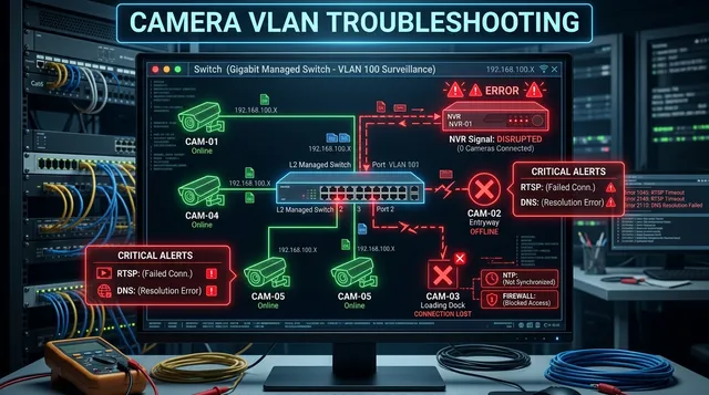
Camera VLAN Not Working: Fix NVR, RTSP, DNS, and Firewall Issues
Diagnose camera VLAN failures when streams, NVR access, NTP, DNS, firewall rules, or isolated mobile viewing stop working.
How to Isolate IP Cameras on a VLAN
A practical local-first guide to isolating IP cameras from your main home network without breaking recording or access.